Callouts: Head opened - how the boards sit in the housing
Source: FCC ID 2APBOAN600, internal-photos exhibit 3999178 (2018 sample), page 1, top photo (808x666)
Annotated image: images/annotated/assembly_open.png
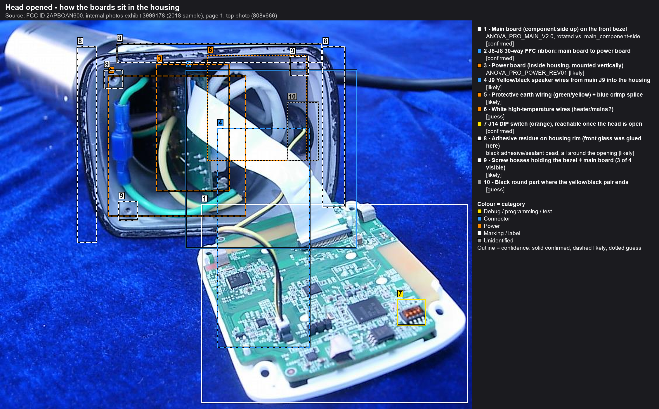
| # | Ref | Identification | Part / marking | Category | Confidence | Notes |
|---|---|---|---|---|---|---|
| 1 | Main board (component side up) on the front bezel | ANOVA_PRO_MAIN_V2.0, rotated vs. main_component-side | Marking / label | confirmed | Board is heat-staked to the white bezel (community report). The component side with all debug points faces into the housing, so it is accessible without de-staking. | |
| 2 | J8-J8 | 30-way FFC ribbon: main board to power board | Connector | confirmed | Release by lifting the grey latch of the FPC socket. Never pull the ribbon. | |
| 3 | Power board (inside housing, mounted vertically) | ANOVA_PRO_POWER_REV01 | Power | likely | ||
| 4 | J9 | Yellow/black speaker wires from main J9 into the housing | Connector | likely | Speaker per a community repair report. Unplug before removing the bezel assembly completely. | |
| 5 | Protective earth wiring (green/yellow) + blue crimp splice | Power | likely | |||
| 6 | White high-temperature wires (heater/mains?) | Power | guess | |||
| 7 | J14 | DIP switch (orange), reachable once the head is open | Debug / programming / test | confirmed | ||
| 8 | Adhesive residue on housing rim (front glass was glued here) | black adhesive/sealant bead, all around the opening | Marking / label | likely | The black glass front is bonded to this rim. Cut the bead with a thin blade, then lift the glass. | |
| 9 | Screw bosses holding the bezel + main board (3 of 4 visible) | Marking / label | likely | Four plastic screws (community report). The 4th boss is hidden behind the ribbon. Matching holes in the white bezel corners. | ||
| 10 | Black round part where the yellow/black pair ends | Unidentified | guess | Probably the speaker (fits the community report), or a grommet. |