Callouts: Power board ANOVA_PRO_POWER_REV01 - bottom side
Source: FCC ID 2APBOAN600, internal-photos exhibit 3999178 (2018 sample), page 3, bottom photo (991x371); flipped top-to-bottom vs. power_top
Annotated image: images/annotated/power_bottom.png
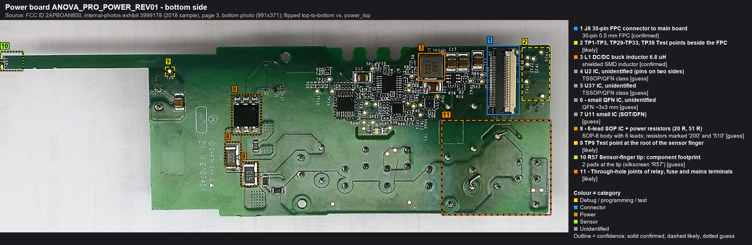
| # | Ref | Identification | Part / marking | Category | Confidence | Notes |
|---|---|---|---|---|---|---|
| 1 | J8 | 30-pin FPC connector to main board | 30-pin 0.5 mm FPC | Connector | confirmed | Ribbon to main board J8. The interface pinout between the boards is a key Phase 1 task. |
| 2 | TP1-TP3, TP29-TP33, TP39 | Test points beside the FPC | Debug / programming / test | likely | Convenient probing of rails and signals entering from the main board. | |
| 3 | L1 | DC/DC buck inductor 6.8 uH | shielded SMD inductor marking: 6R8 / 1822 |
Power | confirmed | Part of a switching regulator with output caps C17/C31. Probably makes the logic rail (3.3 V?) from the AC/DC output. |
| 4 | U2 | IC, unidentified (pins on two sides) | TSSOP/QFN class marking: illegible |
Unidentified | guess | Biggest IC on the power board. Candidates: buck controller, power-board MCU, or sensor AFE. If it is an MCU, it has firmware too, which matters for the update-failure analysis. |
| 5 | U3? | IC, unidentified | TSSOP/QFN class marking: illegible |
Unidentified | guess | |
| 6 | small QFN IC, unidentified | QFN ~3x3 mm | Unidentified | guess | ||
| 7 | U11 | small IC (SOT/DFN) | Unidentified | guess | ||
| 8 | 6-lead SOP IC + power resistors (20 R, 51 R) | SOP-8 body with 6 leads; resistors marked '200' and '510' | Power | guess | Under the AC/DC module area. Missing pins suggest a high-voltage part: offline regulator, triac/MOSFET driver or opto. MAINS POTENTIAL. | |
| 9 | TP9 | Test point at the root of the sensor finger | Debug / programming / test | likely | ||
| 10 | R57 | Sensor-finger tip: component footprint | 2 pads at the tip (silkscreen 'R57') | Sensor | guess | Likely the water-temperature sensor (NTC/thermistor) position. Measure resistance vs. temperature on the real board. |
| 11 | Through-hole joints of relay, fuse and mains terminals | Power | likely | MAINS POTENTIAL. Never probe with the unit plugged in. |