Callouts: Main board - component side - raptox's unit (AN600-20 EU, opened 2026-11-01)
Source: Own photo, raptox's unit, 2026-11-01: images/own/2026-11-01/05_main-board_component-side.jpg (downscaled 3072x4080 -> 1205x1600); markings read from the chips/ close-ups
Annotated image: images/annotated/main_component-side_own.png
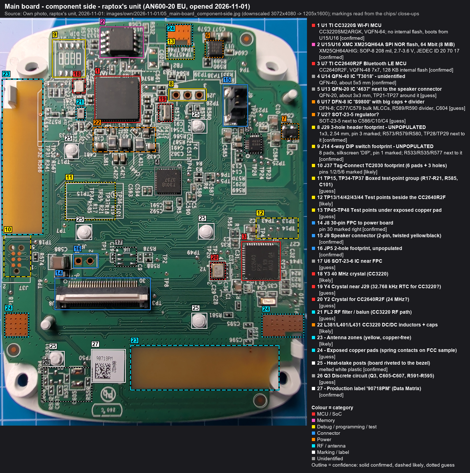
| # | Ref | Identification | Part / marking | Category | Confidence | Notes |
|---|---|---|---|---|---|---|
| 1 | U1 | TI CC3220S Wi-Fi MCU | CC3220SM2ARGK, VQFN-64; no internal flash, boots from U15/U16 marking: CC3220S / M2A / TI 92J / P5KH G4 |
MCU / SoC | confirmed | Refdes U1 read on the board. Date code 92J (FCC sample: different lot). |
| 2 | U15/U16 | XMC XM25QH64A SPI NOR flash, 64 Mbit (8 MiB) | XM25QH64AHIG: SOP-8 208 mil, 2.7-3.6 V, JEDEC ID 20 70 17 marking: XMC / QH64AHIG / P1L09000 20 / 1830C |
Memory | confirmed | CC3220 serial flash: firmware + SimpleLink filesystem. PRIMARY DUMP TARGET. Wide body (208 mil): use a SOIC-8 clip that fits 208 mil. Date code 1830 = 2018 wk 30. |
| 3 | U7 | TI CC2640R2F Bluetooth LE MCU | CC2640R2F, VQFN-48 7x7, 128 KB internal flash marking: CC2640 / R2F / TI 931 / A0J3 G4 |
MCU / SoC | confirmed | |
| 4 | U14 | QFN-40 IC 'T3018' - unidentified | QFN-40, about 5x5 mm marking: T3018 / 3737 |
Unidentified | confirmed | Marking legible but part not identified yet. Central position with many traces toward the LED side: LED/touch driver or a third MCU? Not the Lumissil IS31FL3018 (that is QFN-32). |
| 5 | U13 | QFN-20 IC '4637' next to the speaker connector | QFN-20, about 3x3 mm, TP21-TP27 around it marking: 4637 / 638A |
Unidentified | guess | Location next to J9 (speaker) suggests an audio/speaker driver. Unidentified. |
| 6 | U17 | DFN-8 IC 'S9800' with big caps + divider | DFN-8; C577/C579 bulk MLCCs, R589/R590 divider, C604 marking: S9800 / A0J8 / GAJL (reading uncertain) |
Power | guess | Input/output caps plus a resistor divider look like an adjustable regulator or load switch. Unidentified. |
| 7 | U2? | SOT-23-5 regulator? | SOT-23-5 next to C586/C10/C4 marking: ?CG4 (first char not legible) |
Power | guess | |
| 8 | J29 | 3-hole header footprint - UNPOPULATED | 1x3, 2.54 mm, pin 3 marked; R573/R579/R580, TP28/TP29 next to it | Debug / programming / test | confirmed | Header was fitted on the FCC sample, empty on the production unit. Prime UART candidate (TX/RX/GND). Map by continuity to the CC3220 UART pins. |
| 9 | J14 | 4-way DIP switch footprint - UNPOPULATED | 8 pads, silkscreen 'DIP', pin 1 marked; R533/R535/R577 next to it | Debug / programming / test | confirmed | Switch fitted on the FCC sample only. Strong candidate for the CC3220 SOP boot-mode straps: map the pads to SOP0/1/2 and nRESET. |
| 10 | J37 | Tag-Connect TC2030 footprint (6 pads + 3 holes) | pins 1/2/5/6 marked | Debug / programming / test | likely | JTAG/SWD (CC3220) or cJTAG (CC2640R2F). J38 is the twin on the LED side. |
| 11 | TP15, TP34-TP37 | Boxed test-point group (R17-R21, R585, C101) | Debug / programming / test | guess | Silkscreen box groups 5 test points with series resistors. Production-test or programming access? | |
| 12 | TP13/14/42/43/44 | Test points beside the CC2640R2F | Debug / programming / test | likely | Traces run straight into U7. Candidates: cJTAG (TMSC/TCKC), reset or UART. | |
| 13 | TP45-TP48 | Test points under exposed copper pad | Debug / programming / test | guess | ||
| 14 | J8 | 30-pin FPC to power board | pin 30 marked right | Connector | confirmed | |
| 15 | J9 | Speaker connector (2-pin, twisted yellow/black) | Connector | confirmed | Speaker seen in the housing (label '20 / 219'). | |
| 16 | JP5 | 2-hole footprint, unpopulated | Connector | confirmed | ||
| 17 | U6 | SOT-23-6 IC near FPC | Unidentified | guess | ||
| 18 | Y3 | 40 MHz crystal (CC3220) | marking: T400 / Mc73 |
MCU / SoC | likely | |
| 19 | Y4 | Crystal near J29 (32.768 kHz RTC for CC3220?) | MCU / SoC | guess | ||
| 20 | Y2 | Crystal for CC2640R2F (24 MHz?) | MCU / SoC | guess | ||
| 21 | FL2 | RF filter / balun (CC3220 RF path) | RF / antenna | guess | ||
| 22 | L381/L401/L431 | CC3220 DC/DC inductors + caps | Power | likely | The CC3220 has internal DC/DC converters that need external inductors. | |
| 23 | Antenna zones (yellow, copper-free) | RF / antenna | likely | |||
| 24 | Exposed copper pads (spring contacts on FCC sample) | RF / antenna | guess | The FCC sample had metal spring fingers here. Ground/shield contacts to the housing? | ||
| 25 | Heat-stake posts (board riveted to the bezel) | melted white plastic | Marking / label | confirmed | No need to remove them: everything we need is on this side. | |
| 26 | Q3 | Discrete circuit (Q3, C605-C607, R591-R595) | Unidentified | guess | ||
| 27 | Production label '90718PM' (Data Matrix) | Marking / label | confirmed |